


GE 193X543ABG02电动电路板
1.产 品 资 料 介 绍:
中文资料:
GE 193X543ABG02 是通用电气公司(General Electric)193X 系列工业控制系统中的一款关键电路板,常被称为“电动控制板”或“电动电路板”。该模块广泛应用于 GE 的直流或交流驱动系统中,用于执行电动设备的控制逻辑,包括电机驱动信号处理、反馈调节、系统保护等功能。
该电路板通常作为整个驱动系统的子功能板,配合主控制板、反馈板、励磁板等一起运行,确保设备在工业现场的稳定运行。
技术参数与功能特点
型号:193X543ABG02
产品类型:电动控制电路板(Motor Control PCB)
系统适配:GE 193X 系列工业自动化系统
安装方式:标准插卡式安装,通过金手指接口连接控制框架
输入信号:模拟信号(如电压反馈、电流反馈)、数字逻辑命令、触发控制信号
输出信号:控制信号输出到执行器、驱动器、继电器等
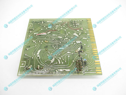
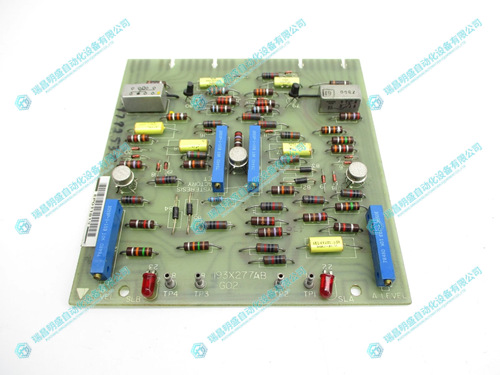
板载元件:集成多个运算放大器、晶体管、调节电位器、电容电阻等分立元器件
调节功能:设有电位器用于调节控制增益、响应时间、补偿参数等
工作电压:通常为 ±15V DC,需由系统统一供电
工作温度范围:-20℃ 至 +70℃,适用于工业现场环境
状态显示:部分版本带有 LED 状态指示灯,便于调试与运行监控
应用场景
GE Mark 系列工业电机控制系统(如 Mark II、IV)
大型直流/交流电机驱动设备
冶金、石化、电厂、水处理、纸浆造纸等过程控制行业
用于执行电动机启停控制、速度调节、状态反馈处理等任务
在旧型 GE 控制系统中的电动子板更换或功能扩展中常被采用
安装与使用注意事项
安装前必须断开系统电源,避免插拔操作中发生短路或电弧
板卡为静电敏感器件,操作时需佩戴防静电手环
所有输入输出信号应严格按系统设计图纸连接,防止控制逻辑异常
初次运行前可使用万用表、示波器检查关键测试点的电压波形和电平
若需调节电位器,应缓慢调节并记录初始设定,以便回退调试值
推荐每 6–12 个月进行一次维护检查,重点关注电容老化、焊点松动、接口接触等问题
英文资料:
GE 193X543ABG02 is a critical circuit board in General Electric's 193X series industrial control systems, often referred to as an "electric control board" or "electric circuit board". This module is widely used in GE's DC or AC drive systems to execute control logic for electric equipment, including motor drive signal processing, feedback regulation, system protection, and other functions.
This circuit board is usually used as a sub functional board of the entire drive system, working together with the main control board, feedback board, excitation board, etc., to ensure the stable operation of the equipment on the industrial site.
Technical parameters and functional characteristics
Model: 193X543ABG02
Product type: Motor Control PCB
System adaptation: GE 193X series industrial automation system
Installation method: Standard card insertion installation, connected to the control framework through a gold finger interface
Input signals: analog signals (such as voltage feedback, current feedback), digital logic commands, trigger control signals
Output signal: Control signal output to actuators, drivers, relays, etc
Onboard components: integrated with multiple operational amplifiers, transistors, adjustable potentiometers, capacitors, resistors, and other standing element devices
Adjustment function: Equipped with a potentiometer for adjusting control gain, response time, compensation parameters, etc
Working voltage: usually ± 15V DC, requiring unified power supply from the system
Working temperature range: -20 ℃ to+70 ℃, suitable for industrial site environment
Status display: Some versions come with LED status indicators for easy debugging and operation monitoring
Application scenarios
GE Mark series industrial motor control system (such as Mark II, IV)
Large DC/AC motor drive equipment
Process control industries such as metallurgy, petrochemicals, power plants, water treatment, pulp and paper manufacturing, etc
Used to perform tasks such as motor start stop control, speed regulation, and status feedback processing
It is often used in the replacement or expansion of electric daughter boards in old GE control systems
Installation and usage precautions
Before installation, the system power must be disconnected to avoid short circuits or arcs during plugging and unplugging operations
The board is a static sensitive device, and an anti-static wristband should be worn during operation
All input and output signals should be strictly connected according to the system design drawings to prevent control logic abnormalities
Before the initial operation, a multimeter and oscilloscope can be used to check the voltage waveform and level of key test points
If the potentiometer needs to be adjusted, it should be slowly adjusted and the initial setting should be recorded in order to roll back the debugging value
It is recommended to conduct maintenance checks every 6-12 months, with a focus on issues such as capacitor aging, loose solder joints, and interface contact
2.产 品 展 示
3.其他产品
4.其他英文产品
Kollmorgen MMC-SD-0.5-230-D servo drive
| K32HCHL-LEK-M2-01 | HH-J715-0000 | BRC-200 |
| K32HCHL-LEK-M2-00 | SS2000IV | IMAS011 |
| K32HCHK-LNK-NS-01 | SV3415-00000 | BRC300 |
| K32HCHK-LNK-NS-00 | SS930-10000 | INICT03A |
| K32HCHK-LEK-M2-01 | 5410-0002 | IMFEC12 |
| K32HCHK-LEK-M2-00 | SLO-SYN230EPI | IEPMU01 |
| K32HCHJ-LNK-NS-01 | SS2000D3 | IMCIS02 |
| K32HCHJ-LNK-NS-00 | SS2000M-D7 | IMDS112 |