

1.产 品 资 料 介 绍:
J6741A-001 处理器模块使用注意事项
J6741A-001处理器模块 英文资料:
Precautions for using J6741A-001 processor module
Wear anti-static wristbands and gloves throughout the module unpacking and installation process to prevent static electricity from penetrating the core computing chip and storage unit.
During installation, align the gold finger guide slot on the device motherboard and smoothly push it in. Tighten the fixed buckles on both sides and strictly prohibit violent insertion or shaking of the module.
Before wiring, carefully check the terminal pin definition table and strictly distinguish between power, communication, and I/O signal ports to prevent module burnout caused by port mixing.
The power supply needs to match the rated voltage specifications of the module. When wiring, confirm that the positive and negative polarities are correct, and use a multimeter to check for any short circuit hazards before powering on.
Shielded twisted pair cables are selected for communication cables, which are routed separately from power cables with a spacing of no less than 20cm to reduce the impact of electromagnetic interference on data transmission.
When connecting expansion modules or peripherals, it is necessary to operate with the system completely powered off, ensuring that the communication bus connector is securely plugged in and the fixing screws are tightened.
The operating environment temperature of the module is controlled between -5 ℃~60 ℃, with a relative humidity of 5%~95% and no condensation. It should be kept away from heat sources, humid areas, and corrosive gases.
Before downloading the control program, it is necessary to back up the original program and parameters to avoid accidental operations that may overwrite critical control logic and affect the normal operation of the system.
After the first power on, observe the status of the running indicator light, which flashes normally without any fault alarm prompts, and then proceed to the next step of program debugging.
During debugging, a step-by-step loading method is used to test the basic communication and I/O point functions first, and then gradually enable the operation control and linkage modules.
Do not plug or unplug any cables or expand modules during module operation to prevent transient current surges from damaging hardware or causing program crashes.
Regularly check the module wiring terminal screws, tighten loose parts, and clean the dust on the cooling fan filter to ensure smooth cooling air ducts.
When cleaning the surface of the module, it is necessary to first disconnect the power supply and gently sweep the dust with a dry soft bristled brush to avoid liquid entering the interior of the module and causing short circuit faults.
When the module is shut down for a long time, disconnect the power supply, seal it in an anti-static packaging bag, store it in a dry and ventilated environment, and maintain it with electricity once a month.
Non professional maintenance personnel are strictly prohibited from disassembling the module casing. When a fault occurs, record the fault code and indicator light status, and contact the manufacturer's technical support in a timely manner.
Summary: The use of the J6741A-001 processor module should focus on anti-static protection, checking wiring specifications, and anti-interference wiring. Program download and debugging should follow the step-by-step operation principle. Daily maintenance should pay attention to heat dissipation, cleaning, and terminal fastening to avoid risky behaviors such as live plugging and illegal disassembly. This can effectively ensure the stability of module operation and system control accuracy.
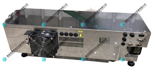
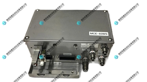
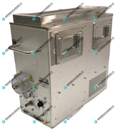
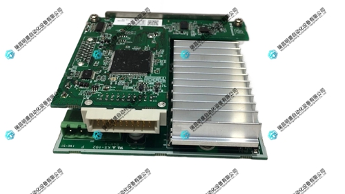
J6741A-001处理器模块 产品展示
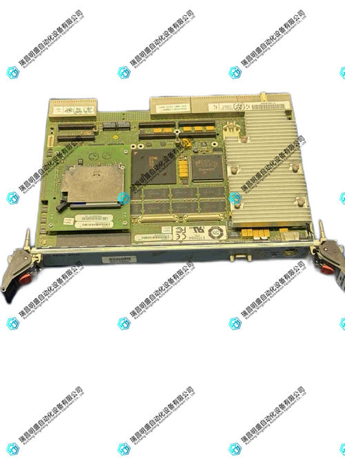
产品视频
3.其他产品
Prosoft 5304-MBP-PDPM控制器模块
B&R 5AP933.215C-00触摸屏
BENTLY 3500/33 149992-01控制卡背板
4.其他英文产品
HIMA F7123 processor input module
TRICONEX FTA-544 17-550544-001B module
TRICONEX FTA-554 base module
| PMB31D-20101-01 | AMAT 0100-20015 | PWM3656-5102-84-3 |
| PMB31D-20101-00 | 07EI60 | N33HLLM-LNK-NS-00 |
| PMB31D-20100-03 | IEMMU11 | 57120001-KY DSTY 101 |
| PMB31D-20100-02 | CI560 | P22NRXC-LNN-NS-00 |
| PMB31D-20100-01 | DI820 | 57160001-K DSDO 110 |
| PMB31D-20100-00 | FPR3323101R1012 | P21NSXB-LNS-NS-02 |
| PMB31D-10216-03 | NIAI05 | 5730032-BE DSDI 110 |
| PMB31D-10216-02 | IPECB11 | P22NSXA-LNN-NS-02 |
The content is from Ruichang Mingsheng Automation Equipment Co., LTD
Contact: +86 15270269218